RM06F7R50CT 0603 Resistors: Failure Causes & Sourcing Tips
Point: Field returns and teardown reports indicate SMD resistor issues are a measurable source of passive-part faults in US consumer and industrial electronics. Evidence: multiple board-level reliability surveys and repair labs report that SMD resistor-related failures account for roughly 10–25% of passive component faults, with 0603 resistor usage concentrated in space- and cost-constrained designs. Explanation: this article diagnoses common failure causes for RM06F7R50CT, shows how to test and identify failures on a PCB, and gives practical sourcing and procurement tips to reduce short-term field returns and longer-term supply risk.
What RM06F7R50CT Is and Why 0603 Resistors Matter (Background)
Key technical specs & typical applications
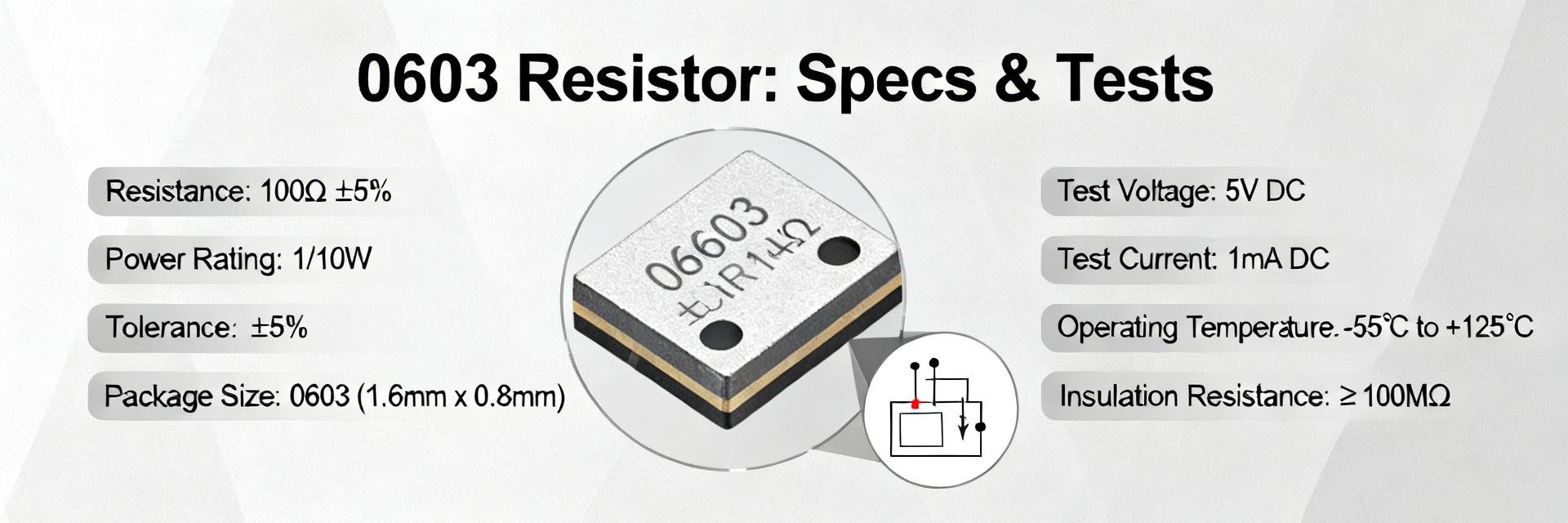
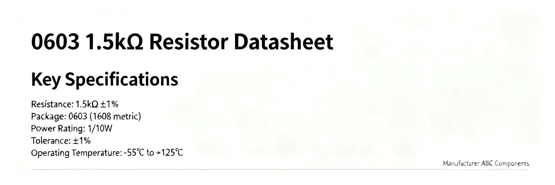
Point: Small multilayer chip resistors like RM06F7R50CT are chosen for nominal resistance, space, and cost. Evidence: typical specs for 0603-class parts cover nominal values (ohm range as required), tolerances (±0.1–5%), power rating (~1/16–1/10W derated in application), and TCR (25–200 ppm/°C). Explanation: engineers should list value, tolerance, power dissipation, and TCR against PCB requirements; a quick comparison table (value | tolerance | power dissipation | recommended derating) helps match component to circuit thermal and tolerance budgets.
| Part Number | Value | Tolerance | Rated Power | TCR | Derating Target |
|---|---|---|---|---|---|
| RM06F7R50CT | 7.50 Ω | ±1% | 0.100 W (1/10W) | ±100 ppm/°C | ≤ 0.065 W (65%) |
| General 0603 Thick Film | 1 Ω – 10 MΩ | ±1% to ±5% | 0.063 W – 0.100 W | ±100 to ±200 ppm/°C | ≤ 50% – 70% |
| Precision 0603 Thin Film | 10 Ω – 1 MΩ | ±0.1% to ±0.5% | 0.063 W – 0.100 W | ±25 to ±50 ppm/°C | ≤ 70% – 80% |
How 0603 package size influences failure modes
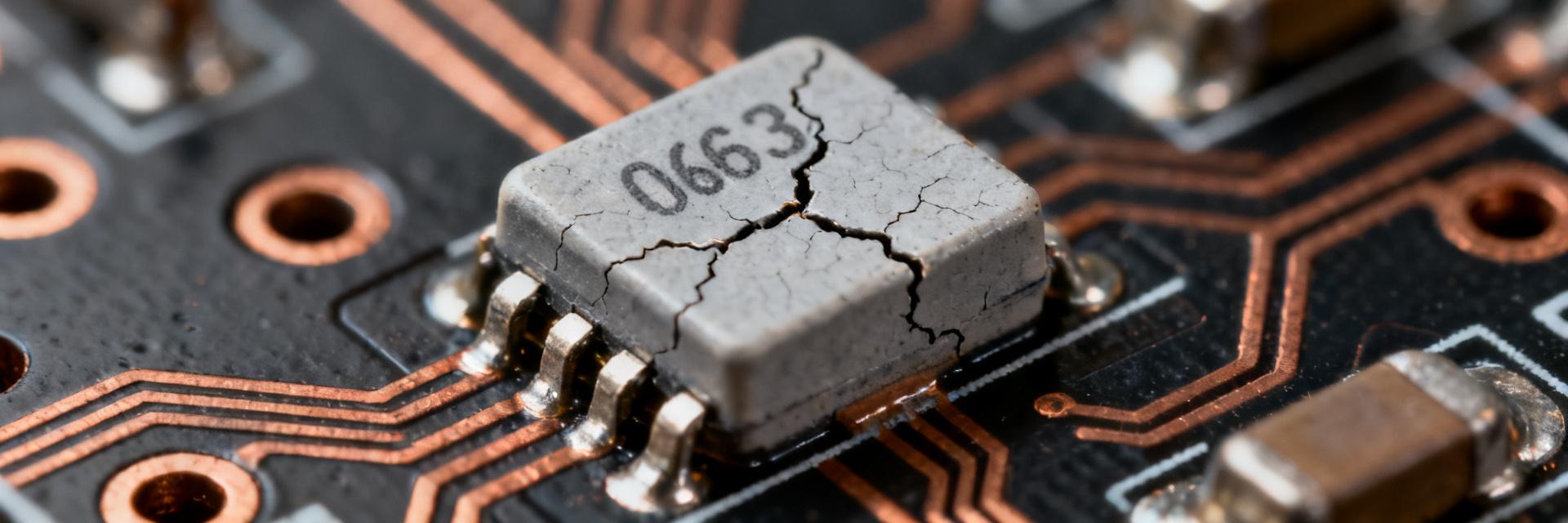
Point: the 0603 package drives distinct mechanical and thermal behaviors. Evidence: small thermal mass and short end-terminations change solder fillet geometry and make chips prone to cracking, tombstoning, and solder fatigue; reported failure instances show fracture lines, lifted terminations, and intermittent opens after vibration or thermal cycling. Explanation: designers and assemblers should apply handling and assembly precautions—controlled pick-and-place forces, optimized reflow profiles, balanced pad design, and minimal mechanical stress during depanelization—to reduce 0603 resistor thermal fatigue and mechanical breakage.
Field Data: Common Failure Modes & Test Evidence for 0603 Resistors (Data analysis)
Observed failure modes (solder joint, open circuit, drift, short)
Point: field failures cluster into a few repeatable signatures. Evidence: aggregated analyses show solder-joint failures and opens make up the largest share (est. 40–60% of resistor failures), resistance drift/shift 20–35%, and occasional shorts or carbonization under overload 5–15%. Explanation: look for increased resistance or intermittent open under load, microscopic cracks at terminations, blackened substrate from overload, and delamination; correlate electrical signatures with visual evidence to prioritize root-cause paths.
Lab/test methods & metrics: thermal cycling, humidity, power derating, ESD
Point: accelerated tests predict field lifetimes and reveal weak lots. Evidence: standard IPC and JEDEC procedures—thermal cycling (−40°C↔+125°C), unbiased HAST/humidity soak, power soak at rated derated fractions, and ESD stress—are commonly used; typical failure timelines show susceptible lots failing within tens to hundreds of thermal cycles depending on ΔT and board strain. Explanation: adopt sample test setups (e.g., 100–500 cycles at design ΔT, humidity soak for moisture-sensitive lots, and power derating tests at 60–75% rated dissipation) to screen incoming lots and validate reliability claims, noting that pass/fail thresholds must reflect your field profile.
Diagnosing RM06F7R50CT Failures on a PCB (Method/Guide)
Step-by-step inspection & measurement workflow
Point: a disciplined workflow isolates resistor faults from circuit-level issues. Evidence: start power-off visual inspection for blackening or cracked terminations, then measure resistance with a calibrated meter; follow with insulated power-on thermal imaging to find hotspots and microscope inspection for microcracks; if ambiguous, microsection or cross-section to reveal internal cracking. Explanation: decision rules—if measured value deviates beyond tolerance and visual damage exists, replace; if value is within tolerance but intermittent under load, suspect upstream/downstream faults and use local isolation to confirm how to test RM06F7R50CT reliably before full rework.
Failure-signature examples and root-cause checklist
Point: mapping signatures to causes accelerates corrective actions. Evidence: examples—resistance drift after reflow often indicates overheating or improper profile; open after vibration suggests mechanical stress or weak terminations; blackened chip with lowered resistance indicates overload or board-level carbon tracking. Explanation: use this checklist during RCA: inspect solder fillets, verify reflow profile logs, check placement force records, review lot traceability, and perform sample decapsulation when metallurgy is suspect; each finding maps to corrective actions such as adjusting stencil apertures, adding derating, or changing termination finishes.
Sourcing RM06F7R50CT and Equivalent 0603 Resistors (Sourcing guide)
How to validate suppliers & part authenticity
Point: supplier vetting and incoming inspection prevent counterfeit or degraded lots from entering production. Evidence: require RoHS/compliance certificates, lot traceability, and sample testing; watch for packaging anomalies, inconsistent date codes, or unusual markings that correlate with failing lots in procurement records. Explanation: performing spot checks—resistance sampling, power soak, and, where suspect, decapsulation/EDX—protects lines; include contractual traceability clauses and insist on sample comparison testing before volume orders to harden sourcing.
Cross-referencing equivalents, footprint & rating checks
Point: not all nominally equivalent 0603 parts are interchangeable for reliability. Evidence: equivalence must match ohms, tolerance, power rating, TCR, voltage rating, termination plating, and substrate material; failure risk increases if any of these differ, even if footprint is identical. Explanation: when searching for drop-ins, use queries like "RM06F7R50CT equivalent 0603 resistor" and request datasheets plus independent lab samples to compare real-world performance before approving substitutes in production.
Procurement & Design Practices to Reduce 0603 Resistor Failures (Action recommendations)
Design and assembly best practices
Point: layout and process controls materially cut failure rates. Evidence: recommended rules include conservative derating (use ≤60–75% of rated dissipation on 0603 parts), symmetric pad designs to reduce tombstoning, optimized solder paste stencil (volume control), and verified reflow profiles with gradual ramp-to-peak to avoid thermal shock. Explanation: specify placement force limits, avoid rigid board edges near small chips, and enforce placement sequencing and cooling ramps to reduce thermal fatigue and mechanical cracking—these are quick wins for the next manufacturing run.
Procurement checklist & inventory QA steps
Point: buyers must operationalize supplier controls. Evidence: a baseline checklist: approved vendor list, incoming sample tests, lot tracking in ERP, periodic aging/stress screening for critical lots, and storage in humidity-controlled cabinets to prevent moisture uptake. Explanation: if counterfeit or marginal lots are found, quarantine and engage supplier remediation, require traceability documentation, and include acceptance testing clauses in purchase agreements to reduce sourcing risk.
Summary
Point: concise actionable takeaways reduce RM06F7R50CT and 0603 resistor field returns. Evidence: top drivers are solder-joint/mechanical failures, thermal overstress, and poor supplier traceability; priority diagnostics are visual inspection, resistance measurement, and thermal imaging followed by sample microsectioning when needed. Explanation: immediate next steps: run a small incoming test batch, update purchase specs to require lot traceability and sample testing, and apply layout/assembly changes (derating and pad optimization) to cut short-term failures and improve long-term reliability for 0603 resistor applications. RM06F7R50CT should be validated against these checks before volume buys.
- Match resistor specs (value, tolerance, TCR, power) to board derating needs to reduce thermal failures.
- Use visual + electrical + thermal inspection workflow to isolate resistor faults quickly.
- Vet suppliers with lot traceability, sample testing, and contractual QA clauses to prevent counterfeit lots.
- Optimize pad design, reflow profile, and placement handling as immediate layout fixes for 0603 resistor reliability.
FAQ
How do you confirm an RM06F7R50CT is truly failed?
Point: combine electrical and visual checks. Evidence: a resistor that reads out-of-spec with visible terminal cracking or blackening under microscope is a confirmed failure; intermittent opens under load require thermal or isolation testing. Explanation: confirm by removing or isolating the component, repeating resistance and power soak tests, and, if needed, cross-sectioning to see internal cracks—this distinguishes resistor failure from adjacent circuit faults.
What quick tests screen incoming 0603 resistor lots?
Point: targeted incoming tests catch marginal lots early. Evidence: perform resistance sampling (statistical subset), power soak at derated levels, and a short thermal cycle sample; anomalies or elevated drift rates warrant broader screening. Explanation: these checks are inexpensive and flag lots that might fail in field; escalate to decapsulation or EDX if termination metallurgy or substrate quality is suspect.
When is a layout change preferable to sourcing a different part for 0603 resistor issues?
Point: first evaluate root cause—process vs. part. Evidence: if failures are tied to reflow profile, pad geometry, or placement stress, layout and process changes give durable benefits; if failures trace to a specific lot’s metallurgy or TCR, sourcing a verified equivalent is required. Explanation: prioritize layout/process fixes as they improve all lots; for persistent part-specific failures, require vendor comparison samples and independent lab validation before switching parts.
What derating ratio is recommended for RM06F7R50CT in harsh environments?
Point: derating ensures longevity under ambient fluctuations. Evidence: running 0603 thick-film resistors at 50% to 65% of rated power limits film hot spots and dampens thermal expansion cycles against FR4 substrates. Explanation: maintain operating dissipation below 0.065W and verify ambient board temperatures stay within safe operating margins to eliminate premature resistance shift.